Tutorials
Video tutorials can be found in our
 YouTube channel.
Additional cookbooks related to GigaMesh on the
Tools for Archaeology and Cuneiform Studies in the Modern Era – TACUME's gitlab page on
Open Educational Resources for 3D.
This is an application-based manual for the GigaMesh Software framework.
It shows basic processing steps typically and also very often used within our projects.
Many of the steps can be combined for more advanced tasks.
Theoretical concepts can be found in the publications section.
For earlier versions of the manual
click here.
Topics found in the manual:
- 00. Video Tutorials
- 01. First Steps
- 02. Labeling and Function Values
- 03. Mesh Cleaning
- 04. Profile Lines and Cross Sections
- 05. Unwrappings
- 06. Extrude Profile Lines
- 07. Distance Visualization
- 08. Distance Measurement between Points
- 09. Volume
- 10. Colorramps
- 11. MSII Filtering - Feature Vectors
- 12. Export Screenshots
- 13. Apply TPS RPM Transformation
05. Unwrappings
There are two alternate tutorials for unwrappings or rollouts on YouTube. The first tutorial shows unwrapping using a cone for a Roman silver jug. The second video demonstrates the rollout using a sphere for an Aryballos. These videos were also published using the Heidelberg Document Repository (heiDOK) having the DOI:10.11588/heidok.00024812 (cone) and DOI:10.11588/heidok.00025128 (sphere). The corresponding publicaiton has the DOI:10.5194/isprsannals-II-5-W1-259-2013.
Meshes can be unwrapped using rotational symmetric geometric primitive using a cylinder, a cone or a sphere.
These unwrappings, which are also known as rollouts or umbrella transformations, are typically applied on objects like pottery.
As the surfaces of real-world objects are often only approximately rotationally symmetric there are distortions to be expected.
The orientation of the object into an upright position is recommended, but not necessary. To store the upright position hit F6 and save the file for later.
5.1 Cone and Cylinder Unwrapping
First the cone has to be defined by interactively selecting its rotational axis and two points on its surface. As the cylinder is a special case of the cone we can use the same procedure, while for a cylinder rollout exist an alternative workflow (shown further down below). To start the definition of the cone use Select -> Cone. Selections are performed by holding the ctrl and a left-click of the mouse. For each of the three definition steps a pictograph (axis, upper point, lower point, cone defined) is shown on the right-hand side. After the cone is defined it can be unwrapped by choosing Edit -> Cone - Unroll Mesh or with a fourth ctrl and left-click the definition process will restart and a new axis will be set.
5.1.1 Choosing the axis
Orientate the object perpendicular on the screen having your view parallel to the rotational axis.
It does not matter if you are looking on the top or the bottom of the object.
With a ctrl plus left-mouse-click you can select the position of the axis, which uses the orientation perpendicular to the screen.
As an alternative the center of the viewport of the screen can be used to select the axis. Therefore you have the center the object in the middle of the screen, which can be assisted using the Polar Grid and the Additional cross-hair found in the tool-bar, which are also present in the Settings menu. When the object is centered using these visual aids choose the button Set the rotational axis using the central pixel or the corresponding menu entry Edit -> Cone - Set Axis Central Pixel. The axis will be shown as a thin green line.
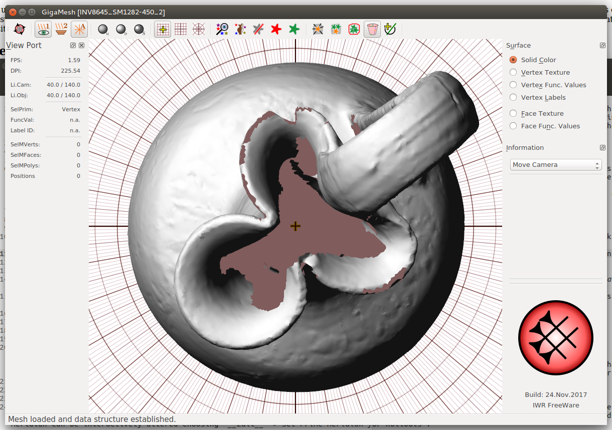
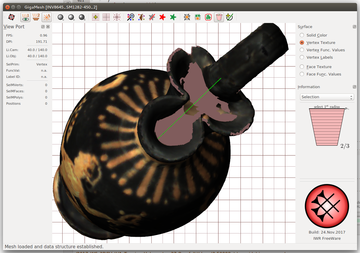
Figure 5.1:
Setting the axis using (a) the perpendicular orientation with polar grid and cross-hair. (b) Defined axis is shown in green color.
5.1.2 Choosing the lower and upper radius
Having the axis defined you have to choose the lower and upper point on the objects surface by ctrl plus left-mouse-click. While the pictograph suggest an order, these points can be chosen out of order as they will be internally swapped automatically. However, the pictograph will only change, when a proper choice was made. When both points were selected the cone will be shown in a red color followed by the question Extend the cone to cover the whole mesh?. If the answer is No, only the part of the mesh between the smaller radius (lower point) and the larger radius (upper point) will be used for the rollout. This is meant for partial unwrapping of objects.
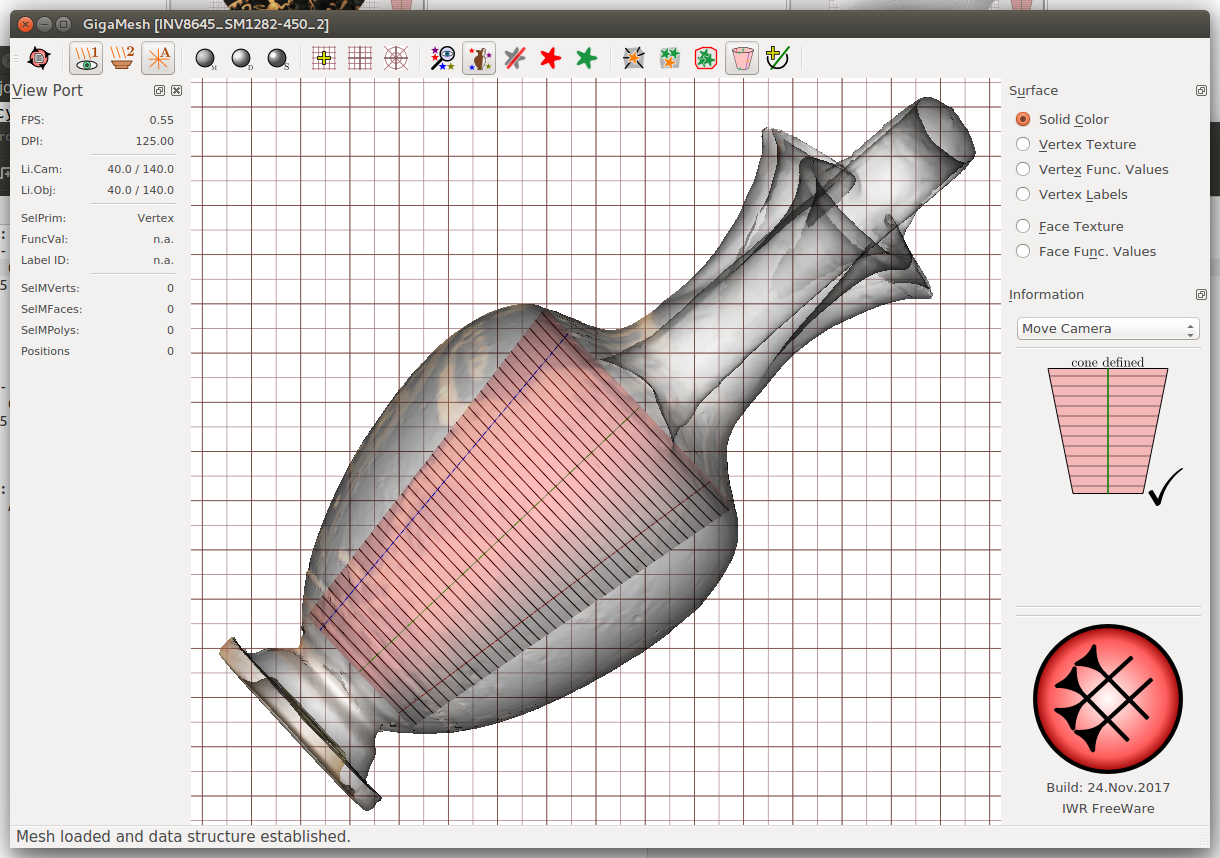
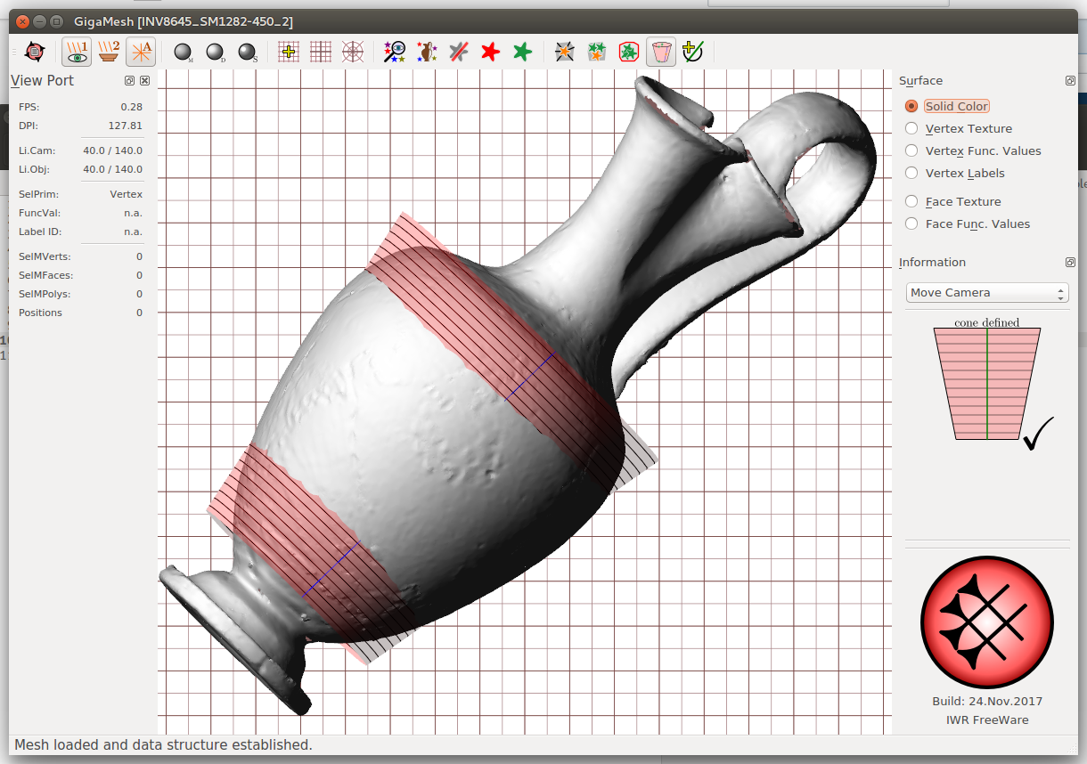
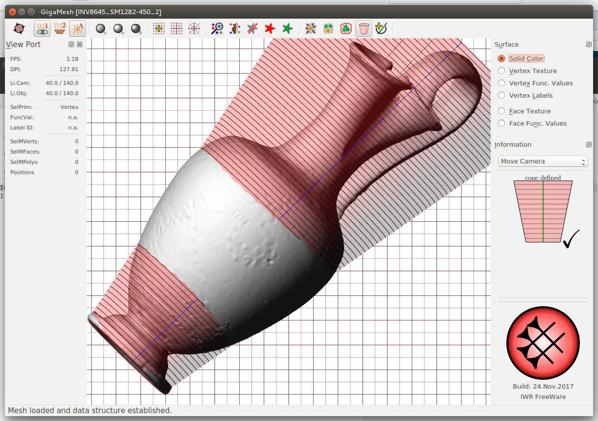
Figure 5.2:
Defined cone (a) with transparent mesh, which was (b) altered using *Edit -> Set Cone Data to have larger radii and (c) extended having the cone covering the whole mesh.*
5.1.3 Choosing the cutting plane i.e. prime meridian
As any rollout requires to cut the mesh you can defined the position using the meridians shown in red and blue color on the cone. The blue line indicates the prime meridian, which should be placed in the center of the front face of your object, because the red line on the opposite (180° meridian) defines the cutting plane. The meridian can be interactively altered choosing Edit -> Set Prime Meridian for Rollouts.
Alternatively the prime meridian and the meridian for the cut can be defined using the selection of a single vertex or face. Therefore change the selection mode to Select -> Primitive - Vertex -- SelVert/SelPrim or Select -> Primitive - Face -- SelFace/SelPrim. Note that the cone will not be shown in this mode unless you return to the cone selection mode. The type of meridian will be chosen later during the rollout.
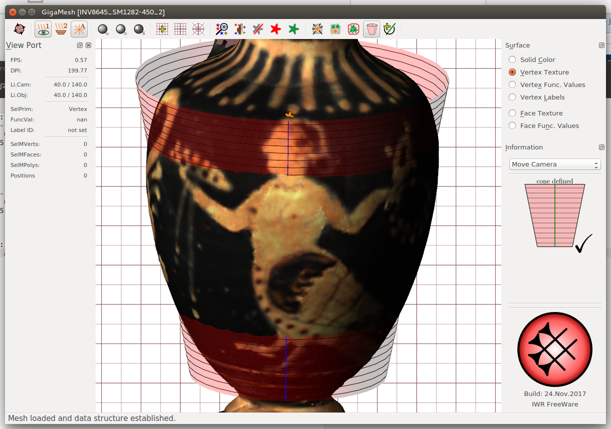
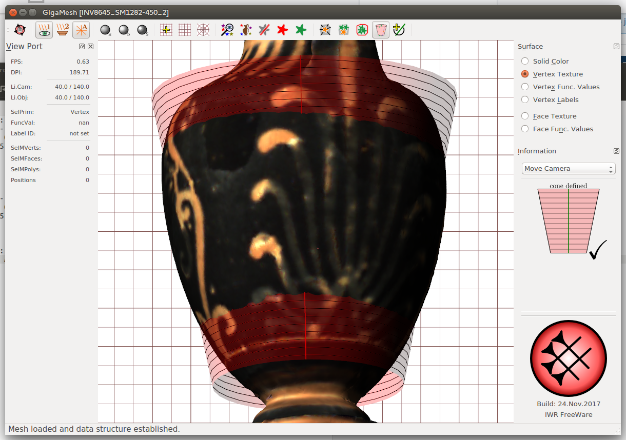
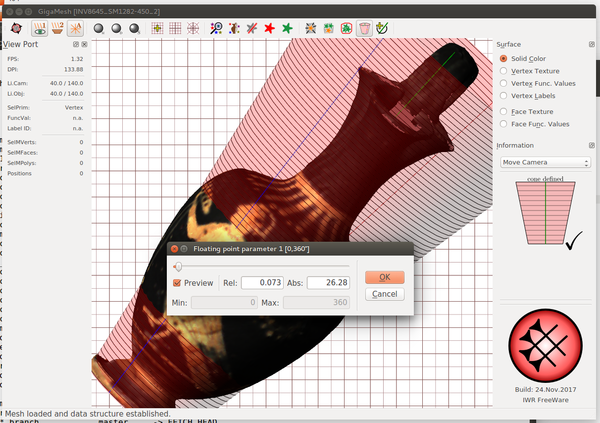
Figure 5.3:
Choosing (a) the prime meridian (blue line) by selecting a single vertex (orange star), which defines (b) the cutting plane on the obverse side (indicated by the red line). (c) Slider for interactive choice of the meridians *Edit -> Set Prime Meridian for Rollouts.*
5.1.4 Cone adjustment and final rollout
The cone can be optionally adjusted by choosing Edit -> Cone - Set Data. When the according dialog is open the cone definition of two points each with a radius will be copied to the clipboard. So you can save it in a text file for documentation or in case you have to repeat the exact same rollout. Having a cone definition in the clipboard and choosing this dialog will automatically use this definition.
Choose Edit -> Cone - Unroll Mesh to perform the unwrapping. This will trigger up to three questions. If a face or vertex was chosen you can use it to set the prime meridian or its opposite meridian to cut the mesh. If you have defined a cone and not a cylinder you will get the option to straighten the rollout as it was a cylinder rollout, which can be repeated later. Finally you can optionally flip the orientation of the rollout by 180° in case the rollout is upside-down. Unless you choose cancel the mesh will be shown with isolines representing the profile lines.
The unwrapped mesh is still a 3D-Model and can be navigated and manipulated normally. Starting from here it is also possible to perform another unwrapping if necessary. Save and reload the model after each unwrapping.
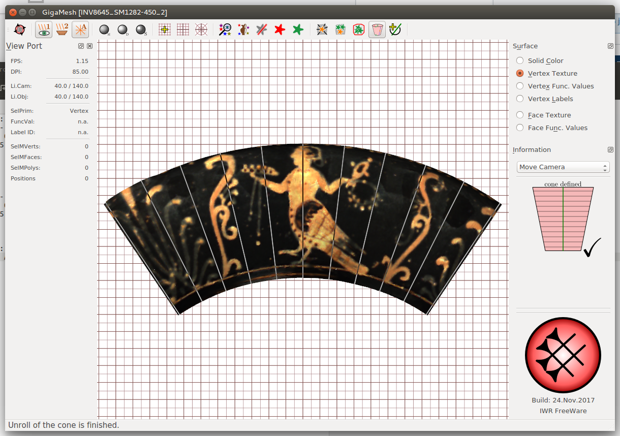
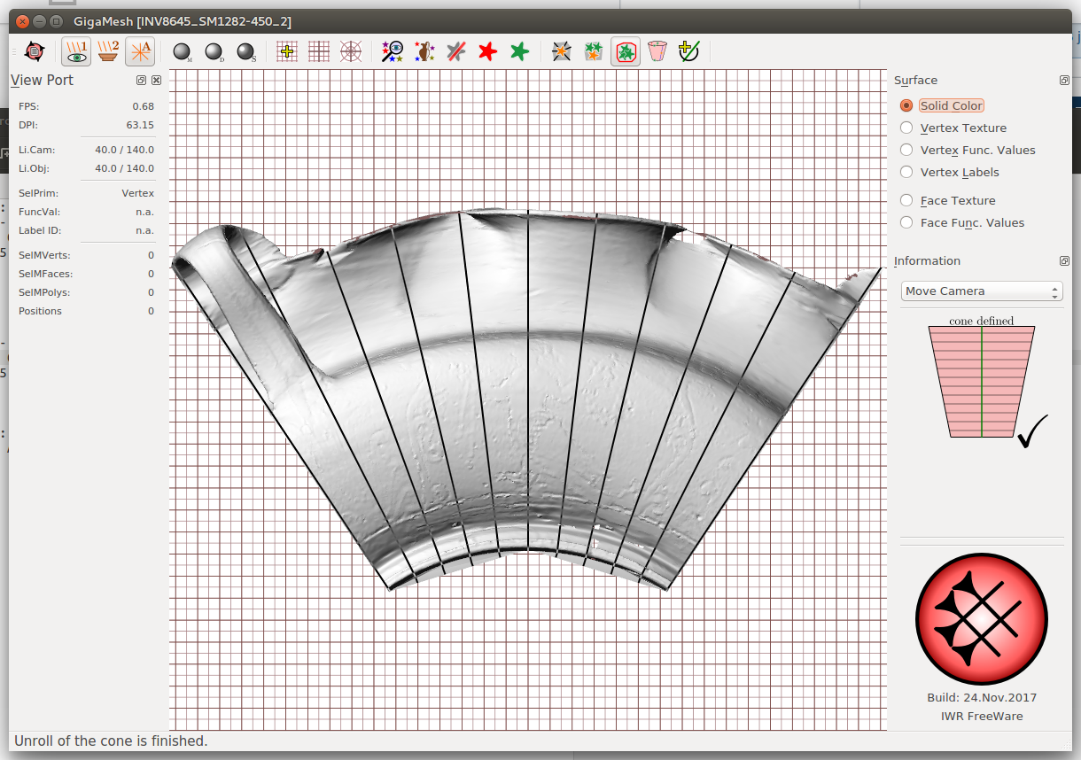
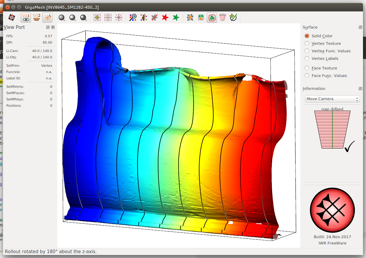
Figure 5.4:
Final rollouts with isolines using (a) only a portion of the mesh and (b) the whole mesh having the cone extended. (c) Straightened rollout using an extra cylinder rollout.
5.2 Sphere Unwrapping
Orientate the object with the rotational axis in vertical position and hit F6. Choose Select -> Sphere, then press and hold ctrl.
Bug: If nothing happens, choose Select -> Cone and Select -> Sphere again.
A sphere can be defined by four points, a sketch of such a sphere appears in the right side bar, showing how many points out of four are already set. While holding ctrl, click on various points at the surface of your model to set these points. When finished, a reddish sphere with horizontal isolines will appear in your workspace.
The next step may be easier if transparency is enabled (View -> Transparency).
In order to unwrap an object, it has to be cut somewhere. Choose Edit -> Set Prime Meridian for Rollouts. Move the slider until the red line on the cone reaches the desired cutting position. Choose Edit -> Sphere - Unroll Mesh to perform the unwrapping. Select the desired surface representation in the right side bar.
The unwrapped mesh is still a 3D-Model and can be navigated and manipulated normally. Starting from here it is also possible to perform another unwrapping if necessary. Save and reload the model after each unwrapping.
5.3 Cylinder Unwrapping
To unwrap an object on a cylindrical surface, set the central pixel of the rotation axis (see Cone Unwrapping). Then choose Edit -> Cylinder - Set Radius. Enter the radius in mm, click OK and choose Edit -> Cylinder - Unroll Mesh. Other than a cone unwrapping, the mesh will be streched and/or compress to fill the cylinder's unrolled surface.